Drafting / scope
The information.
The views. The drawing.
Three related areas of drafting work: turning supplied information into readable views, bringing an existing drawing into CAD and organising a set.
01 / Describe a part
2D technical
drawing.
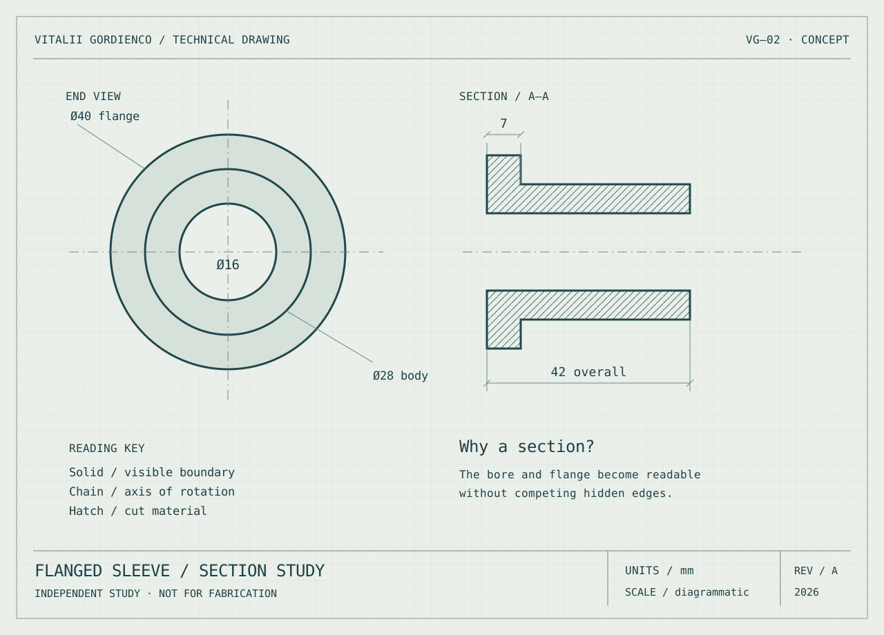
A set of views explains the shape from different directions. A section can reveal what an outside view hides. Dimensions and notes then connect that geometry to the information needed to understand it.
A project can start with a sketch, recorded measurements or an existing drawing. The first task is to establish which information is available and which questions remain open.
- Plan, elevation and detail-view organisation.
- Dimension placement and annotation hierarchy.
- Clear separation of supplied facts and unresolved details.
02 / Revisit the source
CAD redraw.
A paper drawing or scan can be difficult to revise or use consistently. Redrawing it means rebuilding the geometry, organising the annotations and recording what the source actually says.
Missing or contradictory dimensions need clarification. A redraw should not quietly turn an unclear mark into an apparently approved specification. File formats, units and required editability belong in the agreed scope.
- Redraw of supplied sketches or existing drawing information.
- Layer and annotation organisation for a readable file.
- Questions flagged before an uncertain detail is carried forward.
03 / Read the set
Drawing-set
organisation.
A collection of sheets needs an order. Part names, item numbers and revision references help a reader connect the assembly view to the relevant detail.
The scope can include an ordered sheet structure, a clear title block and a consistent way to identify changes. The actual deliverables and review responsibility should be agreed for the specific project.
Explore the Assembly study ↗Define the handover.
A drawing is only part of a useful file package. The intended use determines the formats and checks that matter.
PDF, DWG, DXF or a 3D exchange format can serve different purposes. Required software versions, layers, units, scale and revision identifiers need to be agreed before work starts.
- SOURCE INFORMATION
- Sketches, existing drawings or a description of the available measurements.
- OUTPUT
- The views, sheets and editable formats required for the intended use.
- REVIEW
- Who resolves queries, checks measurements and approves the actual deliverable.
- TECHNICAL APPROVAL
- Engineering calculations, fabrication approval and regulated sign-off require the appropriate separate review.